This ambitious rover project is a childhood dream of mine of building a small Sojourner like rover, fitting it in a rocket, and launching it out into a field where it will survive a couple of nights, or weeks, or however long it'll last. This blog is to document all the lessons learned, occasional failures, and all the fun along the way. To see how this all got started, go to my first post in May 2013.
I am finally done with school! Thank you Anoka Tech, Tom Reid, Daniel Truchon, and Curt Barnier for all of the wonderful knowledge I have gained and can now go out and use! It has been a long journey that all started with this rover project two and a half years ago and has finally lead to a very useful A.A.S. Degree, a membership in Phi Theta Kappa, a membership with the American Institute of Aeronautics and Astronautics (AIAA), and volunteer work with AirSpace Minnesota. And you may already know about presenting the rover at SpaceFest VI thanks to a little push from friend and space author Jay Gallentine. These are all things that I have gotten involved with directly because of following the dream of launching a rover into a field. And of course a lot of help from +Cristin Finnigan who showed me how to believe in myself and to go get my dreams.
So school is finally done but I feel like the real fun stuff is just about to begin. I can now devote more time to the rover and this nifty new 3D printer from Zeepro.
Now, if all goes well with this prototype printer, I can start printing better suspension parts for Inspiration and anything else I can think of that it might need as we progress.
I know I want to create something to reinforce the inside of the rover and hold all of the electronics without being too heavy or in the way and also create parts to allow for steering and better ground clearance. So these will be the next parts that I will be working on.
Over the past couple of months I did manage to spend some time working on Inspiration's battery charging system. You'd think the coding for 4 relays would be pretty straight forward and easy but it turned out to be kind of tricky to get around situations that would cause 2 different if statements to be true and make the relays squeal from trying to be open and closed at the same time. It turns out I did actually over think the problem and just had to change some wiring and greatly simplify the code. Oh which reminds me, now that it's winter and the solar panels don't do much, I bought a Variable DC Power Supply to use for the 12volts or 300mA to charge the batteries during my tests. So far it works great and the Arduino shows them slowly charging and discharging while turning 6 continuous servos. So now I just have to simplify my charging circuit and stuff it into the rover.
That's it for now. Hope everyone is having a great holiday season and I'll catch up with you next year!
I just wanted to quick update those who are following along with the progress of Inspiration. Currently I am taking my last 5 classes at Anoka Tech for an A.S. for Electronics Engineering Technician and working full time at night, so rover work has slowed a bit.
I have figured out, however, how I am going to charge a battery with the solar panel and drive off another one and switch between the two on the fly. I purchased a 4 relay module that the Arduino can control so the batteries can be charged separately, used separately for driving, turned off when not in use, and disconnected from the solar panel in the case that both of them are fully charged.
I'm also still working on the conversion to all servos instead of DC motors and 2 servos. This is taking some time because I need to learn how to program the servo controller so that it does the basic driving commands and also talks to the Arduino.
Another thing in the works is Donald is working on the GPS guidance system so that it can use Google Maps to show were Inspiration is and also the desired way-points that it should travel to. Very exciting stuff!
All of us SpaceFest goers have recently found out that SpaceFest VII will be (tentatively) in June of 2016, so that takes a huge load off of this project since I really wanted to have a lander made up for the next time we possibly display at SpaceFest. Now that I don't need to work on a lander, I can stay focused on really making Inspiration the rover it deserves to be.
I should be done with school in mid December so I plan on really taking off with this project by then. So be patient. These next couple of months probably won't have much for updates but soon there will be very exciting things going on again. Aside from finishing Inspiration, there will be a new blog to follow for the lander and all of its complexities, and then another blog for the liquid fueled rocket! I'm sure things will get crazy with that one. So stay tuned and have fun! Also, if anyone is working on a similar project, I'd love to hear from you!
Well I'm finally done with school for the summer. Amazing how an 8 week 5 credit math class could soak up so much of my time! So I apologize for the delay in progress. I now have a lot more time in the mornings so I think I might be able to get some things done before classes start again in late August. I did manage to get out and do the very first long duration drive over the Solstice weekend in June. That was really exciting because I had the sun's full power and a big open parking lot to drive around in.
So with this test I got to see how much power the solar panels were putting out, how long the battery would last, and also got to test the cooling capabilities of one of the micro fans I had purchased a little while ago.
I had a lot of fun just openly traversing this parking lot.
Not much for obstacles but that's ok. I wasn't there to test the suspension.
As you might have noticed, I replaced the metal detector arm with a small fan.
Since I didn't want to cut a hole for the fan just to find out it didn't cool much, I decided to just use the existing hole and the switchable power normally used for the metal detector for this test. I cycled the fan on and off throughout my drive and each time I cycled it off, the internal temperature would climb to around 100F and with the fan on, it would fall to about 95F. Outside temp was around 75F that day. So the one fan test seems to justify cutting a hole in the side for a fan or two.
This video shows what it looks like from my perspective while operating Inspiration.
You can see the single letter commands put in and then getting the action replied back from the rover letting me know that the command was received and executed.
In this picture you can see I came across a small number 5 in the dirt. Too bad I didn't have the metal detector. It would have been fun to sample something that I didn't put down.
(don't mind the battery voltage, I still don't have that hooked up yet.)
Here I was testing the solar panel output and was greatly saddened to see that in full sunlight, it only had a
20 milliAmp draw on it. I'm assuming the battery was providing all of the power to the systems and so this measured power might have been making it's way to the battery or simply taking 20mA's off of the total load on the battery. At any rate, this was never going to charge the battery like I had intended.
So the plan now for battery charging will be to have another battery on board and a small circuit to charge one battery while the other is being used and then be able to switch between the two. This idea came courtesy of fellow student Shawn Doyle who used such circuits during ComSAT communications in the army. So it's gotta work, right? I know simply charging a battery off of the solar panel works pretty well. Oh another flaw in my design was to have an 8 volt regulator in line with the solar panel to battery so I wouldn't risk exploding the battery with the 12 volts from the panel. Well this definitely limits the power from the solar panels and with the way it's wired up, also limits the power from the battery to the systems. So I think with the new charging circuit, I'll have a relay turn off the solar panels when both batteries are at 8 volts that way I'm not limiting the power through a regulator anymore.
And now onto something that I'm very excited about!
This is the new control panel for Inspiration created by fellow student and LabView wiz, Donald Morgan.
He's been working hard on giving all 27ish commands a functional button. And just yesterday I got to watch him integrate the video feed from the rover and also information sent back, into the sidebar. Really amazing work! This is going to change everything when it comes to demonstrations. I might actually feel comfortable letting people drive it now. (ok, maybe after I add steerable wheels so it doesn't tear itself apart anymore)
Oh, I forgot to mention the results of the long duration drive! Inspiration managed to drive for a total of 45 minutes almost non-stop at top speed before the camera started to get fuzzy. I could have probably turned the camera off and got another 20 minutes out of it but realistically, I won't be able to drive without the camera. Unless it's traveling to a GPS waypoint, then I guess I wouldn't need the camera during that time.
Which reminds me!
I managed to test out the GPS unit the other day. On the balcony, I synced up with 9 satellites and found that my location isn't written in a format that Google maps can use so I need to some how convert it by moving a decimal 2 places to the left and adding a negative to the longitude coordinate. When I did that however, it placed me about 10 miles away. So I guess I have some work to do on that. When I get it figured out, Donald thinks he can get Labview to take the location coordinates and plot a course to the selected waypoint. So technically Labview would be controlling the rover at that point. Which I think is really cool! I'm assuming that should free up the Arduino to keep doing other tasks like monitoring the metal detector, scanning for obstacles with the sonic range finder, and allowing me to move the camera.
Hopefully lots more to come in whats left of my summer break. Stay tuned and have fun!
I know.. it's been a few weeks and I was supposed to go to the Hack Fatory's Minne Maker Faire and then post about it. School and work have kept me a bit busy lately but I can now post a quick bit about what's going on in the world of Inspiration. So +Cristin and I set up a table at the great Minne Maker Faire and showed off Inspiration for all the makers in the area to come and see. Here's some pics of our set up:
Instead of red dirt like we used for SpaceFest, we just grabbed some gravel out of the near by play ground which worked quite well. Lots of people showed up and really enjoyed seeing it moving around and sampling the wrench I had set out for it to detect. Lot's of great ideas and suggestions from people and I managed to write some of them down to pursue later in this project.
But the Maker Faire was awesome! Lot's of great people demonstrating everything from robotics to trebuchets and star trek props (including a functional console and captain's chair!). There's some more pictures from the event located on the Facebook page, https://www.facebook.com/strayrobotics?ref=hl
During the Maker Faire, the room we were in was about 90 degrees so I kept checking the internal temp sensor on Inspiration and found that it got up to 100 degrees inside. I did some quick research on my phone for maximum battery temperature and found a lot of people agreed on 115 degrees before it might burst open. Maybe violently. Sooo.. I set forth on some research for cooling techniques when I got home. One of my favorites was this Peltier Cooler. Actually one smaller but I had no idea this type of technology existed and better yet, in a 1inch square that runs on 5 volts! Problem with that is it also draws around 7 amps which is about 7 amps over budget. So I settled on some fans and found some great 1/2 inch ones to stick in the sides and draw in some cooler outside air. Hopefully it'll work. I'll need to do some tests first before I go cutting holes in the rover but unfortunately I think a lot of this will have to wait until mid July when my math class is over.
Here's a pic of my latest upgrades:
Along with the cooling problem, I also have a ground clearance, turning, and weight problem so I did some more searching for better internal systems. I found some really small Bluetooth transceivers which I hope to replace the XBEE's and their bulky shields. I also think (but not sure yet) that I might be able to send programs to the rover without having to unplug the Arduino from the rover and hook up a USB cable to it. That'll save a lot of time and hassle if that works out. Also for turning, I decided I need the four corner wheels to be steerable so the rover can rotate around easier. I picked up a micro 18 port servo controller so now I should be able to replace the 6 drive motors and camera arm motor with continuous servos and then add 4 servos for steering. This will give me a lot more room inside the rover and create more ground clearance by adding the steering servos to the suspension.
Hopefully I can get to all of this soon. I still need to learn how to program them all, learn to incorporate the ping sensor and gps sensor, draw the new parts, print the new parts, and learn how to put the whole thing to sleep in order to conserve power and charge more rapidly.
Finally caught up on things after SpaceFest VI and my presentation at Anoka Tech this past week. What a great time! First lets start by saying Anoka Tech gave me an 'A' on the project and also an 'A' on the 36 page report I turned in for the project. So that's pretty awesome! I feel like my remaining semester and a half will just be coasting after all of this.
SpaceFest was great! We had our table set up with a little sand box with some obstacles and an IPad showing slides of how this project came to be. We also had a large poster off to the side showing all of the highlights for Inspiration.
We had a visit by a film crew who was going around interviewing people about their displays. That video should be posted fairly soon I suppose. Probably a lot of editing and post production work for them to do yet. But after we finished with them, Rick Tumlinson from Deep Space Industries came over and took a lot of interest in the project and how much time, consideration, and self teaching I put into building Inspiration. I had a lot of fun showing him everything this little rover could do and some of the challenges I over came with some simple coding. I highly recommend checking out DSI and another organization he and many other private space advocates are involved in, spacefrontier.org/
Our little sandbox had a hump to display the suspension and some rocks for effect. The rocks were later used for SCIENCE! by a wonderful little guy named Steven who him and his Dad, Jeremy, spent a considerable about of time with us testing out things like the metal detector's range and what it could detect. We had a lot of fun and I really appreciated being able to test these things since I never actually had time to test them before the trip to Pasadena for SpaceFest.
Here's a quick video from outside SpaceFest to see how Inspiration handles in real dirt and sunlight. I actually found out that the internal temperature was reading up to 95 degrees F. So the gold foil really didn't help keep the sun's heat out like I had hoped. Also, it doesn't handle as well as I wanted so I think this summer I might make the corner wheels steerable and also give it some more ground clearance.
A quick pick of Bobak Ferdowsi (Mohawk Guy) and I after the Curiosity panel at SpaceFest.
Photo courtesy of Jeremy Ditelberg
And here we ran into Steven and his Dad, Jeremy, while we were out "on tour" with Inspiration while the laptop batteries were charging. I'm very excited to see what cool things they'll be up to after spending so much time around all of these inspiring people!
We also got to take Inspiration to NASA JPL where we met with the senior systems engineer for the Sojourner rover, Andrew Mishkin. (who's book, Sojourner, you might recall me using in an earlier post. :-/ ) He was really nice and sat with us in the court yard answering all of our questions on Mars, rovers, project management, and future plans. Him and his wife even stopped by our table to see how the presentation was going! I really can't thank him enough for spending so much time with us.
After our visit with Mr. Mishkin, we got to take part in a JPL tour set up by our friend Jay Gallentine, who writes books on space exploration. We saw where they build their spacecraft, test them, and even where they operate them from! Really exciting stuff!
The little rover that inspired this whole thing
The assembly room
Testing lab
Inside the control room
"Lucky Peanuts" for luck during events
Another author which we met was Frank O'Brien who wrote, The Apollo Guidance Computer: Architecture and Operation, which I am very excited to read since the Apollo add-on for Orbiter Space Flight Simulator uses this computer system pretty extensively. I might even recommend it to my electronics professors for its sections on digital logic. Frank was really nice and very interested in what Inspiration is going to bring for Cristin and I in the future.
Next up for me and Inspiration will be a math class this summer, work in the evenings, and designing a steerable suspension for Inspiration. Plus (finally) testing outside and getting the autonomous part coded and working. Then hopefully I can work on the lander part over the winter. I'm still debating on whether I should make a rocket and lander or just a rocket powered lander to take Inspiration out to its eventual landing site. Anything's possible I guess!
These past couple of weeks have flown by! 2 more weeks and I stuff Inspiration into a box and ship it out to Pasadena for SpaceFest. I've made huge strides on this project but very few pictures to show for it. I'll start off with this one:
I realized that I can sketch on my laptop using my stylus and Autodesk sketchbook. And I also learned I'm not very good at sketching. Kinda fun though!
Next, I tested the 7.4 volt LiPo battery I got from King Kong Hobbies just down the road from me. It's 1/3 of the weight of the 9.6 volt NiMH pack I was using and should drain more consistently. I wasn't sure if it would power all 6 motors, the 9 volt camera, and the 9 volt metal detector. So I tested each one individually and found that each system can be run off of the 7 volts from the LiPo. In fact, here's me testing the camera, motors, and suspension at the same time.. in dirt!
The solar panel wasn't actually hooked up on that video because I still needed to wire the power distribution buss and test to see if the battery could be charged with a solar panel. Here's a pic from a ten minute charging test:
After 10 minutes, each cell had gained .02 volts so this so far confirms my original figure that it should take around 8 hours to charge. I'm still thinking the battery should provide about an hour of drive time. Hopefully I'll get to that test this week. If the weather lets me.
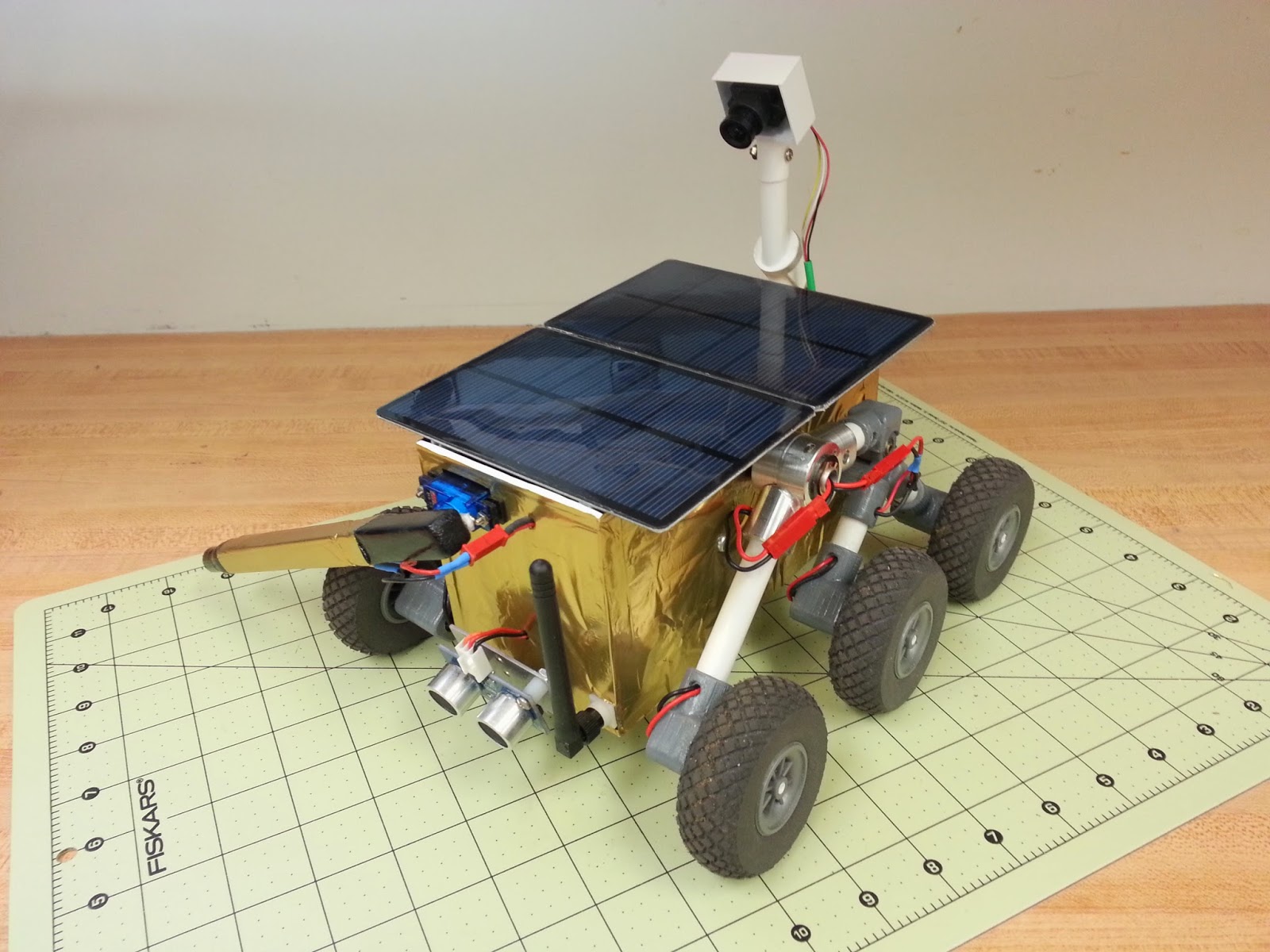
Next I worked on the metal detector. I got the code working, with some help from my classmate Bjorn, and so now when I press 'i' on the keyboard, the Arduino returns the value of "Metallic" or "Non-Metallic". The actual arm that I have completed in this picture is actually balsa wood with the end of the metal detector probe in a rubber cap at the end. I cut the balsa wood where the black and gold part meet, put a small hinge on it, and glued some magnets inside so now it can fold back against the right side of the body and snap into position after landing. The gold is from a gold party balloon that Cristin found at the dollar store. I wanted to make the rover look more like a real NASA rover so I decided to wrap the rover in that. Also, the plan was to keep the sun from cooking the inside of the rover like how the inside of a car gets.
So with Inspiration fully assembled and wrapped in "Mylar", it is ready for more tests and more coding. Still to come will be coding the camera and metal detector to turn on and off with a command in order to conserve battery life and speed charging times. I might even dabble in the GPS this week but I'm kind of thinking I won't have time to get it working before SpaceFest. Hopefully it'll happen. But I will definitely get it outside in the sun soon so stay tuned for those videos.
Oh and I added more to the Inventor drawing that I've been working on. Maybe this summer I'll teach myself how to animate the parts and render so it'll look really professional. I should probably get the sonic range finder drawn in there too I suppose.
Anyways, thanks for the interest in Inspiration and its, at times, slow journey to glory. We're almost there! Stray Robotics will have a table at SpaceFest along with business cards, a banner, a large printed PDF of all of Inspiration's abilities, and of course Inspiration will be maneuvering through a small rock field on the table and possibly showing off a little. Stay tuned! More to come!
This past week I have been incredibly busy getting Inspiration rolling. I cut the aluminum tube down to length and fit it to a U shaped piece of aluminum which will serve as the load bearing part for the body and all of it's components. I then figured out where I wanted the grooves for the retaining rings to go. Putting these grooves in turned into a fairly odd way of machining.
Since I didn't have a lathe handy, I used the next best thing.. a drill press. With a good sharp eye and extremely steady hands, I took a small saw with a .030 blade and held it up to the aluminum tube where I wanted the grooves cut. It actually worked surprisingly well and the .025 thick retaining rings fit in perfectly.
After I got the tube cut and the chassis put together, I took a few pictures of it sitting next to the, now too small, body and then another with a wheel up on it showing the amazing capabilities of Don Bickler's rocker-bogie suspension system.
Once I got it all wired up, I just had to get it outside to do some "victory doughnuts"
It was really nice to finally get it outside in the dirt since the entire time I've been working on this suspension, there has been at least a foot of snow on the ground. There was one issue though with turning around on higher traction surfaces. You'll see in the video how one wheel comes up off the ground. If I continue rotating, the entire suspension side will roll over on the tube and leave the rover kind of laying on its side. So while I've been thinking about how to fix this problem, I started work on the new body.
I went down to the Hack Factory and used their laser cutter to produce some nice accurate cuts and holes for all the wires and screws.
Once I put all the cut pieces together, I mounted the body to the aluminum U with some screws so now the body can be easily separated from the chassis by turning out 4 screws. Here's a couple pics with most of the electronics inside:
This weekend, I set to work on the metal detector arm and reprogramming the speed of the wheels while turning which seems to solve the rolling-over-suspension problem. And just a few hours ago, I finished wiring up one side of the rover so now if I needed to take an arm off for some reason, I just unplug the wires and pull the retaining clip and the whole suspension arm will slide off. A nice modular design just in case I end up designing another system, it can be easily swapped or if I needed to replace a motor, it will make it that much easier.
Next up is wiring the other side and finish the metal detector arm. I also have some more wire harnesses to add to the camera system and the battery.
The ticking clock is really starting to get loud now. I can't believe it's been a month since my last post. Time is really flying by and I still have so much to do. The good thing is, it's actually taking shape. This project was originally something that I thought's I'd spend a couple of months on and then focus on the rocket portion. After a couple of years of trying to build it between school and work, I kind of started to think that I'll never actually finish this rover. It really makes me happy to see it almost finished. Here's some pictures I've taken over this past month:
I had my friend Paul at Paul's Speed & Machine, Inc machine these new aluminum shoulder joints out for me. I asked for 4 and he was nice enough to make 8 just in case I screw up on the holes for the springs. These things are EXACTLY what I drew up on inventor and fit perfectly! Having these work how I planned took a huge burden off of this project. Thanks so much for your help Paul!
These were the parts all laid out. The new shoulder halves, the 5.5 in-lb spring, the 3/8 inch aluminum tube, and the high-performance plastic bushings.
I fought with the springs for a couple of days last week, trying to bend the ends 90 degrees so they would fit in the holes that I had drilled in the shoulder parts. I managed to get this one to work great but then I had difficulty duplicating it on the joint. My biggest problem was getting the ends of the springs bent in the exact right place so that the 2 halves of the shoulder joint would be where I needed them. I decided, after much frustration, that maybe bending the springs was not the way to go and I should just drill some holes so that I don't have to bend the springs at all.
So I settled on drilling at an angle like this. Actually since the drill bit walked a lot, I had to start by drilling straight on with the side of the part and then slowly change the angle until I got what I needed.
Once I got the shoulder joints worked out, I set to work on the aluminum tube and a metal bracket to hang from the tube to then mount the plastic body onto.
I soon decided that the metal bracket should be inside the body so I had to shorten it and re-drill the holes. I've settled on making the rover wider now so that I have more room inside for all the things that are going in there. This means that the current body I have made won't work and will need to be re-designed a little.
I should be getting the retaining clips soon so the suspension should be fully mounted to the tube this week. And after running the wires through the tube, I noticed that I should almost make this thing more modular by adding little wire harnesses to the motor wires up by the shoulders so that way I can just unplug the wires and pull a clip to be able to take the suspension off. And then the plastic body will be screwed onto the metal bracket so that will be removable also.
I started work on the metal detector part as well. I spent almost a week trying to build a very small metal detector circuit but nothing seemed to work right. So I bought one. This thing was perfect for what I needed. I opened it up yesterday and found a nice small circuit that should talk nicely to the Arduino Mega. Oddly enough, it doesn't notice our little Chelyabinsk meteorites we have so I think the metal detector arm will now need a magnet for testing these low iron types of meteorites. (Yes, the Chelyabinsks do stick to a magnet even though there's not much iron in them.)
But anyway, Lots to do yet but it's coming together nicely. One more month to go and then we're off to SpaceFest and NASA JPL to show this off to some people, and then after that, it needs to be ready for presentation for my student project at school. Yikes! Wish me luck world!
Back from a long blog break. When I left off, I was going to the Tucson Gem Show with +Cristin Finnigan. Well we're back now and let me tell you, it's pretty amazing! There were 45 different sites throughout Tucson and each site must have had over 100 vendors at them. We only made it to 2 sites mainly because we made fast friends at Aerolite and Impactika and stuck around to learn a whole bunch about meteorites. We even purchased some. The TSA agent at the airport stopped Cristin and asked if she had rocks in her bag or something. "Space rocks actually!", she enthusiastically replied. We had a blast and will definitely be back! And a big thanks to everyone there for being so wonderful and bringing us into your circle of friends!
As for the rover project.. I received the springs from McMaster and modified the plastic shoulder parts to accept the new larger springs. As I feared, the springs were still too weak to do much good. I calculated that I apply about 2.5 in-lbs of torque on the shoulder joints and the closest spring I could find on McMaster that would remotely fit the parts I have was only good for 2.1 in-lbs of torque. The springs hold the rover up but don't provide enough power to lift the rover up from its launch/landing position. I tried tightening the springs up a little bit but just caused more problems for myself. But I did manage to get the suspension re-mounted and ended up with this:
It became very clear to me that this current set-up I have was not going to be stable enough for the rover to drive straight. Since the shoulder joints are attached to the plastic body, it made the whole assembly very wobbly. So now I've decided to build the rover around the suspension instead of the suspension around the rover. Makes total sense now. Wish I would have thought of it sooner. So now the design is to attach the 2 suspension sides together with an aluminum tube. The tube gets attached to the body and then the shoulder joints will slide over the tube and be locked on with a retaining clip.
Of course this now means I need to redesign the shoulder joints to fit over an aluminum tube. The good thing about a redesign is you can kind of create whatever you want. So I looked on McMaster's site again for springs that are about double the torque I need and bushings to fit over the 3/8 tubing I decided on. The springs I ordered are 5.5 in-lbs of torque and almost twice the size of the previous ones so now the shoulder joints need to be almost twice their original size as well. I immediately set to work on drawing something that would hold the new springs, bushings, and current polystyrene tubing and still be able to do what I want. This new redesign also calls for these parts to be made out of aluminum so I don't have to worry anymore about breaking them. So currently I am waiting for these parts to be made. I have an instructor at the college working on them and I also have them in queue at a friend's machine shop. Of course the machine shop will cost money but I think it'll be worth it in the long run.
After I got the redesign done and now waiting for parts, I started working on mounting the distance sensor and the camera servo and arm. This is what I've got so far:
The suspension is still being held on by giant shaft collars so the solar panel doesn't sit down all the way, but you get the idea. Oh, and I decided to upgrade to the Arduino Mega for more inputs and outputs since I'll be needing them for the distance sensor, camera arm, temp sensor, battery sensor, GPS, and metal detector. (Wow, I have a lot to do yet!)
Here's a really quick video of the camera arm in motion.
I've made the arm look a bit nicer since I did this video and I'm working on a nice way to mount the camera to it as well. Also, because of the way the arm is mounted now, I think it'll be best for it to lay down over the solar panel instead of out back like it does in this video. I think it will also help a lot with the lander design later.
I've been very busy trying out the suspension parts. First I got all of them printed.
Then an hour of freeing them all from the support material
Then I fit them all together with the wheels and springs in the shoulder parts.
Then I routed the wires through the tubes and fit the suspension on the body.
After getting the suspension on, I found that the springs were not strong enough to hold the weight of the rover so the body sank to the table and things were a little sloppy in the shoulder joint so the wheels slid out away from the body as well.
I tried tightening the springs but started to break the printed parts. I got some assistance from some guys at work and we decided to replace the plastic shaft in the shoulder with a metal rolling pin. Today I set to work on that and found it all fits really well! The bearing now fits better on the shaft but the spring still couldn't be wound up enough to provide good torque. A professor at school suggested torsion springs instead so I did the math for how much torque was needed from the spring and set to ordering them on McMaster. Hopefully that will work out. I'm also in the process of making an aluminum U shaped bracket to hold both sides of the suspension to each other for better rigidity. More to come next week. Off to the Tucson Gem Show for the weekend!


+and+Steven+Ditelberg.JPG)